

Choosing the right Compressor begins with understanding application, not chasing a popular brand.
A rotary screw unit may quietly run a factory’s pneumatic tools, while a reciprocating compressor handles short, high-pressure bursts. Centrifugal, scroll, rotary vane, axial, diaphragm, and other designs solve different engineering problems. Each choice affects pressure stability, oil carryover, noise, maintenance, and electricity use.
The U.S. Department of Energy reports that compressed air can represent a significant share of industrial electricity consumption. Its compressed-air guidance also identifies leaks, artificial demand, and poor controls as common sources of waste. The Compressed Air and Gas Institute (CAGI) adds practical comparison data through standardized performance verification programs. Meanwhile, MarketsandMarkets’ 2024 industry analysis projects continued growth in the global compressor market, driven by manufacturing, energy, healthcare, and process industries.
The details matter.
As compressed-air specialist Ron Marshall has stated, “Compressed air is not free.” That short warning remains highly relevant. A machine that costs less to purchase may consume more power every hour. A quiet scroll Compressor can suit a dental clinic, but it may fail under continuous factory demand. A centrifugal system can deliver enormous flow, yet it needs careful operating control and stable loading.
No ranking is absolute. This guide compares the top ten compressor types by design, pressure range, efficiency, maintenance needs, and practical use. Some categories overlap, and real installations rarely fit a perfect list. That is where judgment matters. Expect useful distinctions, but verify every recommendation against duty cycle, air quality, operating temperature, and lifecycle cost.
ISO 1217 does not rank compressor technologies. It defines acceptance testing for delivered flow, pressure, power, temperature, and measurement uncertainty. Its performance classes describe test reliability, not machine design. Class 1 generally requires tighter accuracy than Class 2. This distinction prevents misleading comparisons. The U.S. Department of Energy reports that compressed air may consume about 10% of industrial electricity, depending on site conditions and operating practices (DOE, Improving Compressed Air System Performance). Small efficiency errors can become expensive.
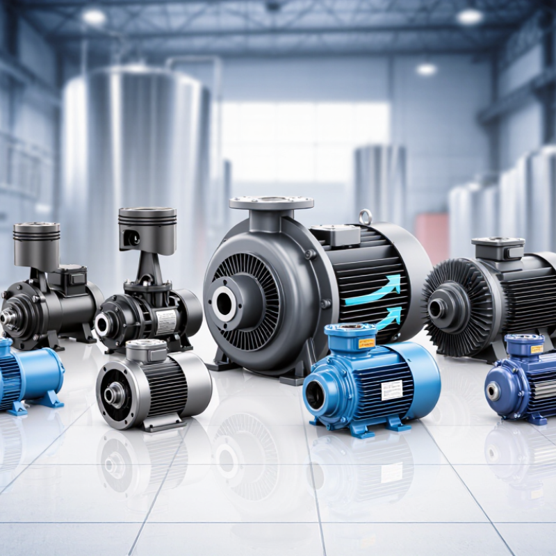
The ten common types are defined by their compression mechanism. Reciprocating compressors use pistons for high pressure and intermittent demand. Rotary screw compressors use meshing rotors for steady plant air. Rotary vane units use sliding vanes in an eccentric rotor. Scroll compressors compress air between orbiting spiral elements. Centrifugal compressors add velocity with impellers, then convert it into pressure. Axial compressors move air along a shaft through repeated blade rows. Diaphragm compressors isolate gas with a flexible membrane. Liquid-ring compressors use a rotating liquid seal and handle wet gases well. Roots blowers move fixed volumes with lobed rotors, usually at lower pressure. Turbo-compressors use dynamic rotating stages for large, continuous flows. ISO 1217 testing should state inlet conditions and cooling arrangements clearly. Otherwise, the comparison remains incomplete.
A practical weakness exists here: published efficiency figures may not reflect part-load operation, leaks, pressure drops, or maintenance. Industry field studies repeatedly identify these factors as major sources of wasted energy.
The ten widely used compressor types include reciprocating piston, diaphragm, rotary-screw, rotary-vane, scroll, centrifugal, axial, roots-lobe, liquid-ring, and turbo compressors. Each design serves a different pressure, flow, and gas-quality requirement. In practical plant work, I would not choose equipment by pressure alone. Temperature, duty cycle, moisture, oil tolerance, and maintenance access matter just as much.
Reciprocating compressors suit high-pressure, lower-flow service, often reaching 1,000 bar in specialized systems. They deliver strong compression but produce pulsation, vibration, and more wearing parts. Diaphragm compressors isolate the gas from lubricated components. That makes them valuable for clean, toxic, reactive, or high-purity gases. Their flow is usually limited, and the diaphragm needs careful inspection. Small leaks can become serious process problems.
Rotary-screw compressors provide steady flow with fewer pulsations. They commonly support plant air and process duties from low pressure into moderate industrial ranges, often below 40 bar per stage. They run smoothly, but heat management and oil separation require attention. At 1–1,000 bar, multistage designs, intercooling, and specialized seals may be necessary. Centrifugal units favor large flows and moderate pressure, while scroll compressors suit clean, quiet, smaller systems. Real installations are less tidy. A compressor that looks ideal on paper may perform poorly when demand changes sharply or maintenance is delayed.
What Are the Top 10 Types of Compressors?
Assess Vane, Scroll, Roots, and Liquid-Ring Compressors at 0.5–15 bar
At 0.5–15 bar, compressor selection depends on flow stability, gas cleanliness, and duty cycle. Sliding-vane compressors suit steady, moderate-pressure air service with compact layouts. Scroll compressors provide oil-free gas and low vibration, but their capacity range is often narrower. Roots compressors deliver nearly pulse-free flow and respond well to low-pressure, high-volume duties. Liquid-ring compressors tolerate wet or contaminated gases better, although seal-liquid temperature affects performance.
Pressure alone does not decide the winner. Field audits should compare free-air delivery, specific power, discharge temperature, and maintenance hours. The U.S. Department of Energy reports that compressed-air leaks can waste 20–30% of compressor output. That figure makes system leakage more important than a small efficiency difference. Check the pipes, too.
The boundary is less tidy. A 7-bar scroll unit may outperform a vane machine at partial load, while a liquid-ring design may be safer for humid gas. Roots equipment can become inefficient when pushed toward its upper pressure limit. ISO 1217 testing helps standardize capacity and power measurements, but site conditions still change results. The International Energy Agency identifies motor-driven systems as a major industrial electricity load, reinforcing the value of whole-system measurements. A neat ranking can mislead. Measure real demand before choosing from the ten main compressor types.
Comparative overview of common compressor technologies used within or near the 0.5–15 bar discharge-pressure range. Values are typical engineering ranges rather than universal limits; actual performance depends on gas composition, inlet conditions, temperature, speed, and configuration.
| Rank | Compressor Type | Compression Principle | Typical Discharge Pressure | Typical Capacity Range | Oil Management | Key Strengths | Common Limitations | Best-Fit Applications in This Range |
|---|---|---|---|---|---|---|---|---|
| 1 | Rotary Screw Compressor | Two intermeshing helical rotors continuously trap and reduce gas volume. | 3–15 bar | Approximately 0.1–100 m³/min | Oil-injected or oil-free designs available. | Continuous duty, steady flow, compact installation, low pulsation. | Oil-injected models require separation and oil-control equipment; turndown can affect efficiency. | Factory air, process air, pneumatic tools, refrigeration, and general plant utilities. |
| 2 | Reciprocating Piston Compressor | A piston compresses gas inside a cylinder through suction and discharge valves. | 2–15 bar and above | Approximately 0.01–30 m³/min | Lubricated or oil-free versions available. | High pressure capability, strong part-load flexibility, and good efficiency at lower flow rates. | Pulsating flow, vibration, more wearing parts, and higher maintenance requirements. | Workshop air, gas boosting, filling systems, laboratory service, and intermittent operation. |
| 3 | Scroll Compressor | One fixed and one orbiting scroll progressively compress gas in pockets. | 2–12 bar | Approximately 0.02–10 m³/min | Commonly oil-free in the compression chamber; some systems use lubricated bearings. | Quiet operation, low vibration, compact size, and clean compressed gas. | Limited capacity per module; sensitive to liquid carryover and contamination. | Medical air, dental systems, electronics, small process lines, and clean-room utilities. |
| 4 | Rotary Vane Compressor | Sliding vanes in an eccentric rotor reduce the volume of sealed gas chambers. | 1–10 bar | Approximately 0.02–25 m³/min | Usually oil-lubricated; oil-free configurations are available for selected duties. | Smooth flow, compact construction, reliable low-to-medium pressure operation. | Vane wear, oil carryover, and sensitivity to unsuitable gas temperatures or contamination. | Packaging, vacuum-pressure service, pneumatic conveying, and small industrial plants. |
| 5 | Roots Blower | Two synchronized lobed rotors move a nearly fixed volume of gas from inlet to outlet. | 0.5–3 bar | Approximately 0.1–10,000 m³/h | Compression chamber is generally oil-free; bearings and gears are lubricated separately. | Simple, robust, oil-free gas delivery, and suitable for high flow at low pressure. | Low pressure ratio per stage, relatively high noise, and declining efficiency as pressure rises. | Wastewater aeration, pneumatic conveying, combustion air, and low-pressure process gas. |
| 6 | Liquid-Ring Compressor | A rotating impeller forms a liquid ring that seals and compresses gas pockets. | 0.5–8 bar | Approximately 0.1–1,500 m³/min | Process liquid provides sealing; liquid separation, cooling, and recirculation may be required. | Handles wet, dirty, condensable, or corrosive gas better than many dry compressors. | Lower efficiency, process-liquid consumption, and limited pressure ratio per stage. | Chemical processing, vapor recovery, priming, gas extraction, and wet gas service. |
| 7 | Centrifugal Compressor | A high-speed impeller converts velocity into pressure through a diffuser and collector. | 2–15 bar | Approximately 500–100,000 m³/h | Often oil-free in the gas path; gearbox or bearing systems may require lubrication. | Very high flow, continuous operation, low vibration, and low maintenance at stable load. | Efficiency falls at low flow; surge control is required and inlet conditions are important. | Large air plants, process gas, refrigeration, combustion air, and utility systems. |
| 8 | Diaphragm Compressor | A flexible diaphragm separates the drive mechanism from the compressed gas. | 1–15 bar and above | Approximately 0.001–10 m³/min | Gas chamber can be oil-free because the diaphragm provides separation. | High gas purity, leak minimization, and suitability for toxic, corrosive, or valuable gases. | Low capacity, pulsation, diaphragm fatigue, and higher cost for larger flow rates. | Hydrogen, specialty gases, laboratory systems, sampling, and chemical processing. |
| 9 | Rotary Claw Compressor | Non-contacting claw rotors trap and compress gas without internal lubrication. | 0.5–4 bar | Approximately 0.05–20 m³/min | Oil-free compression chamber; bearings and gears are isolated from the gas path. | Dry, clean operation, low maintenance, and good reliability for moderate pressure duties. | Lower pressure range than many screw or piston compressors; performance depends on clearances. | Vacuum-pressure combinations, pneumatic conveying, packaging, and clean industrial air. |
| 10 | Axial-Flow Compressor | Multiple rotating and stationary blade rows progressively raise gas pressure. | 3–15 bar overall, usually through multiple stages | Approximately 10,000–1,000,000 m³/h | Typically oil-free in the gas path; bearing and accessory systems may be lubricated. | Extremely high flow capacity and strong performance in large, steady-load installations. | Complex design, high initial cost, narrow stable operating range, and poor suitability for small systems. | Large combustion-air systems, gas turbines, air separation, and major process facilities. |
Selection note: For a practical choice, compare required flow, discharge pressure, duty cycle, gas composition, allowable oil content, inlet temperature, noise limits, and maintenance access. Pressure values shown are typical discharge ranges and should be verified against the compressor's performance curve for the intended operating point.
What Are the Top 10 Types of Compressors?
Among the ten main compressor types, centrifugal, axial, and jet designs reveal the clearest flow differences. Centrifugal compressors move gas radially outward through an impeller. Their pressure ratio is moderate per stage, often around 1.1 to 1.5 in industrial service. Axial compressors keep flow parallel to the shaft. Multiple stages can deliver a high overall pressure ratio, but small clearances increase sensitivity to fouling, stall, and changing conditions.
Jet compressors use a high-velocity motive fluid to entrain and compress another stream. They have no rotating shaft. That sounds simple. However, their pressure ratio is usually limited. Efficiency depends strongly on nozzle design, suction pressure, and motive-fluid conditions. They suit duties where reliability and low maintenance matter more than peak efficiency.
A reliable comparison needs measured inlet temperature, mass flow, discharge pressure, and gas composition. Pressure ratio alone can mislead. A centrifugal unit may handle variable flow better, while an axial unit can move enormous volumes near its design point. Jet compressors tolerate harsh environments, but their energy demand is often underestimated. I have seen performance estimates drift when operators used catalog conditions instead of site data. That mistake is common and worth challenging. Engineers should verify surge margin, choke limits, leakage, and acoustic levels during selection and commissioning.
Typical pressure ratio and volumetric-flow capacity by compressor type
Dynamic compressors such as axial and centrifugal machines handle the highest flow rates, while reciprocating and screw compressors generally achieve higher pressure ratios in compact systems. Jet compressors and Roots blowers operate at lower pressure ratios and are often selected for specific gas-handling or high-volume applications. Values shown are representative industrial ranges and vary with staging, speed, gas properties, and operating conditions.
For a broad industrial comparison, I rank ten compressor types using ASME PTC 10 testing principles, efficiency, flow range, and maintenance evidence. The ranking is practical, not absolute. PTC 10 results depend on gas composition, inlet temperature, pressure ratio, speed, and test uncertainty.
1. Centrifugal compressors deliver strong efficiency at steady, high flow. They need clean gas and careful surge control.
2. Reciprocating compressors handle high pressure and changing loads well, but valves, rings, and lubrication increase maintenance.
3. Rotary screw compressors offer reliable medium-flow service with simple capacity control. Oil separation remains important.
4. Axial compressors provide exceptional flow and efficiency at scale, yet their operating range is narrow.
5. Scroll compressors run quietly, with few wearing parts, but their flow and pressure capacity stay limited. The ranking is practical.
6. Mixed-flow compressors balance pressure and volume, though performance data can be less familiar to operators.
7. Liquid-ring compressors tolerate wet gas and contamination, but seal-liquid use reduces overall efficiency.
8. Diaphragm compressors protect gas purity and limit leakage, while diaphragm fatigue demands scheduled inspection.
9. Rotary-vane compressors are compact and responsive, but vane wear and oil management can become costly.
10. Roots or lobe compressors provide dependable low-pressure air movement, although their compression efficiency is modest.
Field records often challenge laboratory results. A clean centrifugal unit may outperform its rating, while poor filtration changes everything. I would revise this ranking for each plant after reviewing flow logs, power readings, vibration trends, and actual maintenance hours. Some data still arrives incomplete. That weakness matters.
All products and services provided by Innovative Plastic Molders, Inc. will meet or exceed our customer's perceived requirements and expectations. We will listen and respond to what our customers are telling us in a timely and forthright manner.

ISO 9001:2015 CERTIFIED
© Copyright 2009 – Innovative Plastic Molders, Inc.
Website by Central 8 Marketing
10451 Dog Leg Road Ste 200
Vandalia, OH 45377
Phone: 937.898.3775
Fax: 937.535.0640
Email: sale@endtheplastic.com

