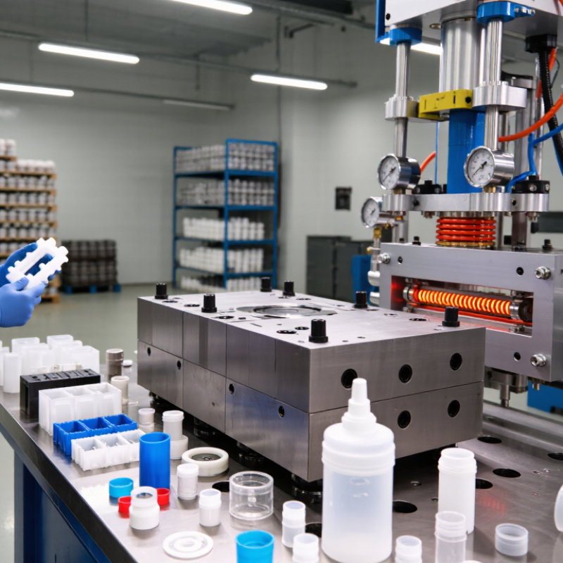
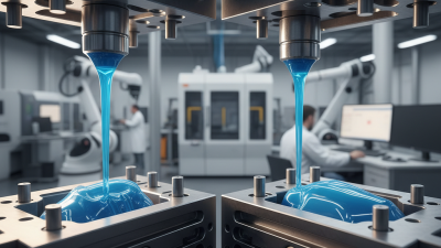
Injection molding is one of the most widely used methods for producing consistent plastic parts, from medical housings and automotive clips to bottle caps and electronic enclosures. Its basic idea is simple: plastic pellets are heated until they melt, then pushed under pressure into a shaped mold. After cooling, the mold opens, and the finished part is ejected.
John Bozzelli, founder of Scientific Molding, often reminds manufacturers, “The mold is the heart of the injection molding process.” This practical observation explains why successful production depends on more than a powerful machine. The material, mold design, temperature, pressure, cooling time, and ejection system must work together. A small change in moisture, wall thickness, or cooling conditions can create warping, sink marks, short shots, or visible flow lines.
The cycle usually includes clamping, injection, packing, cooling, and ejection. Each stage leaves evidence on the part. A technician may inspect the gate, measure dimensions, or compare the surface finish under bright light. That hands-on review matters because simulation and machine data cannot reveal every production problem.
Injection molding is efficient, but it is not automatically perfect. Poor design decisions can increase waste, energy use, and tooling costs. Even experienced teams sometimes adjust a process repeatedly before finding stable settings. Understanding how the process works helps engineers question assumptions, choose suitable materials, and build parts that perform reliably in real conditions.
Injection molding is a manufacturing process that creates plastic parts in large quantities. It begins with small polymer pellets, which are heated until they become a thick, flowing material. A machine pushes this material into a shaped mold under controlled pressure. The mold cools the plastic and gives it a precise form. After opening, the finished part is removed, and the cycle starts again.
The mold defines the part’s dimensions, surface texture, and functional details. Engineers must consider wall thickness, cooling channels, air vents, and shrinkage during design. Even a small design error can cause warping, sink marks, short shots, or difficult ejection. In production practice, technicians monitor temperature, injection speed, pressure, and cooling time. These measurements help maintain consistent results between cycles.
Injection molding is efficient, but it is not foolproof. Material moisture, uneven cooling, or worn tooling can reduce quality. A reliable process needs regular inspections and properly recorded settings. I would not judge a molded part by appearance alone. Its strength, fit, and dimensional accuracy also matter. The process can produce simple covers, detailed housings, and complex technical components, but each application requires careful testing before full-scale production.
Injection molding starts with small polymer pellets. A heated barrel melts them, then a screw pushes the material into a steel mold. Cooling fixes the final shape. Material selection controls nearly every result, including strength, surface finish, cycle time, and cost.
Thermoplastics are the main choice because they soften again when reheated. Polypropylene suits lightweight housings and living hinges. ABS offers impact resistance and a clean appearance. Polyamide handles heat and mechanical loads, although it can absorb moisture before molding. Polycarbonate provides high impact strength, while POM supports low-friction moving parts. For demanding heat exposure, engineers may consider PEEK, but its processing window is narrow and its cost is substantial.
Recycled polymers can reduce virgin material demand. However, repeated heating may lower molecular weight and consistency. The OECD’s Global Plastics Outlook reported that only about 9% of plastic waste was recycled globally in 2019. That figure deserves caution when evaluating recycled feedstock. Its quality depends on sorting, contamination, drying, and the intended application. PlasticsEurope’s Plastics—The Fast Facts 2024 reported global plastics production of approximately 414 million tonnes in 2023. The scale is enormous. A small material mistake can multiply across millions of molded parts. In practice, designers should test shrinkage, moisture behavior, weld lines, and recycled-content variation before approving production. That step is often underestimated.
| Category | Process Stage or Material | Typical Data or Range | How It Works or Key Properties | Common Applications |
|---|---|---|---|---|
| Process Overview | Injection molding | Thermoplastic-focused process High-volume production method |
Plastic pellets are heated until they flow, injected into a mold under pressure, cooled until solid, and then ejected as a molded part. | Housings, containers, fittings, closures, automotive components, medical parts, and consumer products. |
| Step 1 | Material feeding and drying | Pellets are supplied through a hopper. Drying temperature and time depend on the polymer. |
Moisture-sensitive materials must be dried before processing to reduce bubbles, splay, hydrolysis, and loss of mechanical performance. | Especially important for polyamide, polycarbonate, PET, PBT, and other hygroscopic materials. |
| Step 2 | Plasticizing | Typical melt-temperature range: approximately 160–400°C, depending on the material. | A rotating screw conveys, compresses, and melts the pellets. The screw also meters the required shot size for the next cycle. | Provides a uniform melt before injection into the mold cavity. |
| Step 3 | Mold closing and clamping | Clamping force may range from less than 10 tonnes to several thousand tonnes. | The two mold halves are closed and held together so that injection pressure does not force the mold open or create excessive flash. | Clamping-force requirements depend on projected part area, cavity pressure, material, and mold design. |
| Step 4 | Injection and filling | Injection pressure commonly ranges from about 50 to 200 MPa, depending on part and material. | The screw moves forward and pushes molten plastic through the nozzle, sprue, runners, and gates into the cavity. | Filling speed and pressure influence weld lines, air traps, orientation, surface finish, and dimensional accuracy. |
| Step 5 | Packing and holding | Usually applied after initial cavity filling and before the gate freezes. | Additional pressure compensates for material shrinkage while the part cools, improving weight, surface quality, and dimensional stability. | Important for reducing sink marks and maintaining consistent part dimensions. |
| Step 6 | Cooling | Cycle time may range from a few seconds to several minutes. | Cooling channels remove heat from the mold. The part must become sufficiently rigid before ejection. | Cooling time is strongly affected by wall thickness, mold temperature, polymer type, and cooling-channel design. |
| Step 7 | Mold opening and ejection | Mechanical ejector pins, sleeves, or stripper plates are commonly used. | The mold opens and the solidified part is released. The cycle then repeats automatically or semi-automatically. | Proper draft angles and balanced ejection help prevent deformation and part damage. |
| Thermoplastic | Polypropylene (PP) | Density: approximately 0.90–0.91 g/cm³ Melting range: approximately 160–170°C |
Lightweight, chemically resistant, fatigue-resistant, and suitable for living hinges. It has relatively low stiffness compared with reinforced polymers. | Caps, food containers, storage products, appliance components, automotive trim, and living-hinge parts. |
| Thermoplastic | Polyethylene (PE) | Density: approximately 0.91–0.97 g/cm³, depending on grade Melting range: approximately 105–135°C |
Good chemical and moisture resistance with low friction. Low-density grades are more flexible; high-density grades are stiffer. | Bottles, caps, bins, containers, toys, piping components, and household products. |
| Thermoplastic | Acrylonitrile butadiene styrene (ABS) | Density: approximately 1.02–1.08 g/cm³ Typical processing melt range: approximately 220–270°C |
Good impact strength, rigidity, dimensional stability, and surface appearance. It is generally not recommended for prolonged outdoor exposure without stabilization. | Equipment housings, instrument panels, consumer products, enclosures, and interior components. |
| Thermoplastic | Polystyrene (PS) | Density: approximately 1.04–1.06 g/cm³ Typical processing melt range: approximately 180–250°C |
Easy to process, dimensionally stable, and available in rigid or impact-modified forms. General-purpose grades can be relatively brittle. | Disposable items, laboratory products, packaging components, housings, and trays. |
| Thermoplastic | Polycarbonate (PC) | Density: approximately 1.20 g/cm³ Typical processing melt range: approximately 260–320°C |
High impact resistance, good transparency, and useful heat resistance. It is moisture-sensitive and usually requires pre-drying. | Safety glazing, transparent covers, electrical components, optical parts, and protective equipment. |
| Thermoplastic | Polyamide (PA, nylon) | Density: approximately 1.01–1.15 g/cm³ for common unfilled grades Typical processing melt range: approximately 220–300°C |
Good strength, wear resistance, and fatigue performance. It absorbs moisture, which can change dimensions and mechanical properties. | Gears, bearings, cable ties, structural components, clips, and under-hood parts. |
| Thermoplastic | Polyoxymethylene (POM) | Density: approximately 1.41–1.43 g/cm³ Typical processing melt range: approximately 180–220°C |
High stiffness, low friction, good wear resistance, and strong dimensional stability. It is well suited to precision molded parts. | Gears, bushings, fasteners, valve components, handles, and precision mechanisms. |
| Thermoplastic | Polyethylene terephthalate (PET) | Density: approximately 1.33–1.40 g/cm³ Typical processing melt range: approximately 250–290°C |
Good strength, chemical resistance, and barrier performance. PET is moisture-sensitive and often processed using careful drying and temperature control. | Bottles, jars, packaging preforms, films, and engineering components. |
| Thermoplastic | Thermoplastic polyurethane (TPU) | Density: approximately 1.10–1.30 g/cm³ Shore hardness commonly ranges from about 70A to 95A |
Flexible, elastic, abrasion-resistant, and available in a broad range of hardness levels. Processing conditions vary significantly by formulation. | Seals, flexible grips, wheels, protective covers, footwear components, and cable-related parts. |
| High-Performance Polymer | Polyether ether ketone (PEEK) | Density: approximately 1.30–1.32 g/cm³ Typical melt-processing range: approximately 340–400°C |
High temperature resistance, chemical resistance, wear performance, and mechanical strength. It requires specialized equipment and tightly controlled processing. | Demanding aerospace, medical, chemical-processing, electrical, and precision-engineering components. |
| Material Formulation | Glass-fiber-reinforced thermoplastics | Common reinforcement levels: approximately 10–50% by weight | Glass fibers can increase stiffness, strength, heat resistance, and dimensional stability, but may increase shrinkage anisotropy and tool wear. | Structural housings, brackets, automotive components, appliance parts, and industrial equipment. |
| Material Formulation | Additives and colorants | Use and concentration depend on the required performance and polymer system. | Stabilizers, flame retardants, lubricants, impact modifiers, nucleating agents, and pigments can change processing behavior and final properties. | UV-exposed parts, flame-rated electrical parts, colored products, wear-resistant components, and specialty applications. |
| Design Factor | Wall thickness and draft | Uniform walls are preferred; draft is commonly about 0.5–2° or more, depending on texture and depth. | Uniform wall thickness reduces warpage and sink marks. Draft angles help the molded part release from the cavity and core. | Applied to housings, covers, containers, structural parts, and textured surfaces. |
| Quality Factor | Common molding defects | Examples: short shot, flash, sink mark, warpage, weld line, burn mark, void, and splay. | Defects can result from incorrect temperature, pressure, speed, cooling, venting, moisture control, mold design, or material selection. | Process monitoring and design-for-manufacturing reviews help reduce scrap and improve repeatability. |

How Does the Injection Molding Process Work?
Injection molding begins with small plastic pellets placed into a hopper. The pellets move into a heated barrel, where controlled heat softens them. A rotating screw mixes the material and pushes it forward. Temperature, pressure, and screw speed must match the material’s behavior. Small errors can create bubbles, weak areas, or uneven surfaces.
The screw then injects the molten plastic into a closed mold. The mold contains the product’s detailed cavity, including ribs, holes, and textured surfaces. Hydraulic or electric force keeps the mold shut during filling. Sensors can monitor pressure and temperature during this stage. The plastic cools against the mold walls and gradually becomes solid. Cooling takes time.
The mold opens after the part reaches suitable stiffness. Ejector pins push it onto a collection area, while runners and gates may require trimming. Operators inspect dimensions, color, flash, and surface quality. In practice, the process is rarely perfect. Warping may appear when cooling is uneven, and excessive pressure can leave stress marks. A skilled technician may adjust the mold temperature, injection speed, or holding pressure after reviewing test parts. That adjustment matters because two molds with similar designs can behave differently. Careful records, repeat measurements, and material checks make production more reliable.
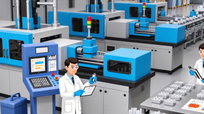
Injection molding machines are commonly classified by their drive system: hydraulic, all-electric, and hybrid. Hydraulic machines use pumps and fluid pressure to move the screw and clamp the mold. They remain useful for large parts and demanding clamping forces. All-electric machines use servo motors, offering precise control, lower noise, and cleaner operation. Hybrid machines combine hydraulic force with electric control. This classification is practical, but not perfectly clean.
Plastics Europe’s Plastics—The Fast Facts 2023 reported global plastics production of about 400.3 million tonnes in 2022. That volume supports demand for faster, more repeatable molding equipment. Grand View Research’s 2024 Injection Molding Machine Market report also identifies electric and hybrid systems as important growth areas. Electric machines can reduce energy waste during repeated cycles. However, their purchase price may be higher. Hydraulic systems can still make better economic sense for heavy parts, long production runs, or older factory layouts. The right choice depends on material, mold size, cycle time, and maintenance skills.
Tips: Check actual energy consumption at the intended cycle, not only the machine’s brochure rating. Measure clamp force carefully. Too much force can damage molds and waste power. Ask operators about setup time and cleaning access. A technically advanced machine can underperform when training is weak. That is an uncomfortable, but common, production lesson.
Injection molding forces molten polymer into a precision-machined cavity, producing identical parts at high speed. It suits medical housings, automotive clips, and appliance panels. Once tooling is ready, each additional part can become relatively inexpensive. Fortune Business Insights estimated the global injection molding machine market at USD 15.43 billion in 2023. That scale reflects strong demand for repeatable production, not automatic efficiency.
The limitations appear before production begins. A complex mold may require costly design, testing, and maintenance. Tooling changes can delay a project by weeks. Cooling also consumes significant cycle time. Poor venting, uneven walls, or incorrect temperatures may create sink marks, warpage, or short shots. These defects waste material and labor. PlasticsEurope reported 413.8 million tonnes of global plastics production in 2023. The figure shows the industry’s scale, but it also raises a harder question: is high-volume production always the right choice? Sometimes, it is not.
Tips: Confirm expected volume before ordering tooling. Use uniform wall thickness where possible. Request mold-flow analysis for complex geometry. Recycled resin may reduce impact, but it can change color, strength, and consistency. Test it carefully. A practical review should measure scrap, energy, maintenance, and part quality together. Cost savings on paper can disappear beside a warm mold, rejected parts, and repeated adjustments.
All products and services provided by Innovative Plastic Molders, Inc. will meet or exceed our customer's perceived requirements and expectations. We will listen and respond to what our customers are telling us in a timely and forthright manner.

ISO 9001:2015 CERTIFIED
© Copyright 2009 – Innovative Plastic Molders, Inc.
Website by Central 8 Marketing
10451 Dog Leg Road Ste 200
Vandalia, OH 45377
Phone: 937.898.3775
Fax: 937.535.0640
Email: sale@endtheplastic.com