

Choosing Zinc Die Cast Parts begins with the job they must perform, not the alloy name on a quote. A compact latch, electrical connector, or decorative housing may need different strength, tolerances, and surface finishes. Start with the load, operating temperature, exposure to moisture, expected production volume, and available space. Small details matter. A thin wall or awkward parting line can affect both tooling cost and consistency.
Market growth makes supplier selection more important, but it does not prove zinc suits every project. Grand View Research’s 2024 analysis estimated the global die casting market at USD 76.5 billion in 2023, with projected annual growth of 6.1% through 2030. That figure covers die casting broadly, not zinc alone. For practical design checks, the North American Die Casting Association’s Product Specification Standards offer industry guidance on dimensions and tolerances. Ask suppliers how their proposed alloy, tooling, and inspection plan meet your drawing’s requirements. Request samples where appearance or fit is critical. A polished prototype can still hide production problems.
Compare more than unit price. Review tooling ownership, cycle expectations, finishing steps, and quality documentation. Confirm that critical dimensions can be measured reliably. Then check whether the supplier has made parts with similar geometry and end-use demands. These checks take time. They can also expose a trade-off: a design that looks efficient on screen may be difficult to cast consistently. No single checklist removes uncertainty, and early estimates can change after tooling review. Treat them as starting points, not promises.
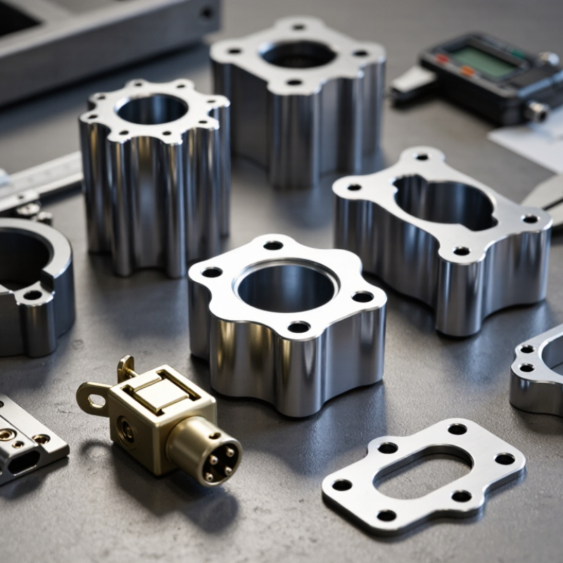
Before comparing zinc die cast parts, write down what the component must do in service. Does it carry a load, locate another part, shield electronics, or move repeatedly? A small hinge, for example, may face thousands of cycles, while a connector housing may mainly need stable alignment. Those jobs call for different priorities.
Record the expected forces, duty cycle, temperature range, and surrounding conditions. Include occasional shocks, vibration, moisture, and contact with other materials. These details can affect strength, wear, corrosion resistance, and dimensional stability. Check where fasteners will sit and whether thin walls or sharp corners could create weak areas. Fit matters, too. A few tenths of a millimeter may change how a mating component assembles, so confirm critical dimensions with the engineering team and the casting supplier.
Be specific. “Warm environment” is not enough; note the expected temperature and exposure time. If the part will bear load, define the load and how often it occurs. Then review the requirements against prototype measurements and, where practical, functional testing. Early calculations help, but real parts can still reveal unexpected stress or fit issues. That’s worth admitting before tooling decisions are locked in.
Zinc alloys can look similar in a parts list, but their behavior under load differs. Zamak 3 is a common baseline, offering a useful balance of strength, ductility, and casting consistency. It suits housings, covers, and components with modest loads. Its ductility can help a part tolerate minor impact without cracking, though geometry still matters.
Zamak 5 adds copper for greater strength and hardness. That can benefit threaded bosses, levers, or parts exposed to repeated contact. The trade-off is reduced ductility, so thin sections or sharp corners may be less forgiving. ZA-8 can provide higher strength than common Zamak grades, but check casting requirements and production constraints before specifying it. Stronger is not automatically better.
Corrosion resistance depends on the alloy, surface finish, and environment. Zinc alloys generally perform well in ordinary indoor and atmospheric conditions, while salt spray, persistent moisture, or chemicals can change the picture. A coating may help, but it cannot compensate for every design weakness. Look closely at seams and recessed areas where moisture can linger. Test representative parts when exposure is uncertain. Datasheets narrow the choice; they rarely settle it completely.
Zinc die casting suits compact parts with detailed features, but geometry should guide the process choice. Start with the part’s job: identify load points, mating surfaces, and areas that need a clean finish. Then mark the required wall thicknesses and transitions on a section drawing. Abrupt changes can create uneven cooling and sink marks. Small details matter.
Draft angle, parting lines, and ejection space affect both tool design and the finished shape. Give walls enough draft for reliable release, especially around deep pockets and tall ribs. Place the parting line away from sealing faces or visible surfaces when possible. A side opening may require a slide in the die, adding tool complexity and maintenance. Keep it practical.
Ribs can strengthen thin walls without adding a bulky section, while rounded corners help metal flow and reduce sharp stress points. Avoid crowded bosses and narrow gaps that restrict filling or complicate machining. Check tolerances against the actual function: a locating bore may need secondary machining, while a noncritical outer face may not. Review a 3D model with the die caster before freezing the design. One detail is easy to miss: the ideal geometry on screen may leave too little room for gates, vents, or ejector pins. Be ready to revise it.
How to Choose Zinc Die Cast Parts for Your Project
Evaluate the actual surface, fit, and inspection requirements before approving a zinc die cast design. A bright sample can hide problems: thin plating may reveal pores, while a heavy coating can soften edges or affect fit. Specify the finish and its measurable acceptance criteria, such as a surface roughness Ra limit, instead of relying on “smooth.” Small details matter.
Set tolerances around function. ISO 8062-3:2023 provides casting tolerance grades from CT1 to CT16, but the appropriate grade depends on the process and feature. NADCA’s Product Specification Standards offer die-casting tolerances by alloy and dimension. Use these references with your supplier to assess critical holes, mating faces, and dimensions after finishing. A blanket tolerance may look tidy on a drawing, yet create unnecessary cost—or miss a real fit issue.
Tips: Mark critical dimensions clearly, and state whether inspection happens before or after coating. Ask for first-article measurements and a finish sample. Check parts under the lighting and viewing distance used in service; appearance can be subjective, and I would not approve it from a single polished sample alone.
| Selection Factor | Typical Guidance | What to Specify | How to Verify |
|---|---|---|---|
| Alloy and application | Zinc alloys such as Zamak 3 and Zamak 5 are commonly used for detailed, thin-wall components. Alloy choice affects strength, ductility, casting behavior, and finishing response. | State the required alloy designation, service loads, operating temperature, environment, and any applicable material specification. Do not rely on a generic “zinc alloy” description. | Review the material certificate and confirm that the specified alloy matches the drawing and purchase requirements. |
| As-cast surface | A well-controlled die can produce a smooth, detailed surface, but texture, flow marks, parting lines, ejector marks, and local porosity may vary with geometry and process conditions. | Identify cosmetic faces, acceptable witness marks, texture requirements, and areas that may be trimmed or machined. Add reference samples or clear visual acceptance criteria when appearance is critical. | Inspect cosmetic surfaces under defined lighting and viewing conditions. Check first articles and production samples against the agreed criteria. |
| Plating | Nickel- or chrome-based decorative plating may be suitable for appearance and wear requirements, but casting porosity and surface preparation can affect coating quality and consistency. | Specify the coating system, required thickness, appearance, corrosion-performance test, masked areas, and allowable surface defects. Confirm that the process is suitable for the selected zinc alloy. | Use coating-thickness measurement, visual inspection, and the agreed corrosion test. Define test method, duration, and acceptance criteria in the specification. |
| Paint or powder coating | Paint and powder coatings can provide color and environmental protection. Adhesion depends on cleaning, pretreatment, part geometry, and coating cure conditions. | Specify coating type, color reference, gloss or texture, coverage, thickness range, masking, and adhesion requirements. Identify edges, recesses, and threads that need special attention. | Check color and appearance against an approved standard. Verify coating thickness and adhesion using the agreed test method and sampling plan. |
| Dimensional tolerances | Achievable tolerances depend on part size, geometry, alloy, die design, tool condition, and measurement method. Tight tolerances can increase tooling and inspection costs. | Apply tolerances to functional features rather than tightening every dimension. Identify datum references, critical-to-function dimensions, and any dimensions requiring machining. | Measure critical features with suitable calibrated equipment. Review the drawing’s datum scheme and confirm measurement methods before production approval. |
| General casting tolerances | Use a recognized casting-tolerance framework, such as ISO 8062-3 or applicable NADCA product standards, as a starting point. The selected grade and scope must suit the part and process. | Call out the standard, edition, tolerance grade, and any exceptions on the drawing or purchase specification. Agree on requirements with the foundry before tooling release. | Compare inspection results with the agreed drawing and standard. Resolve any conflict between general notes and explicitly toleranced dimensions before production. |
| Parting line and flash | Parting lines and small amounts of flash are normal process considerations. Their location and allowable size should not interfere with assembly, sealing, safety, or appearance. | Show preferred parting-line locations, flash limits, trim requirements, and no-flash zones. Include sealing surfaces and mating interfaces as controlled features. | Inspect trim quality and critical interfaces. Use functional assembly checks where dimensional inspection alone does not confirm fit. |
| Porosity and pressure integrity | Porosity may occur in castings and can affect pressure retention, plating, appearance, or machining. The acceptable level depends on the part’s function and process. | State whether the part must be pressure-tight, plated, or machined through a wall. Define any porosity limits or repair restrictions rather than assuming zero porosity. | Use an agreed leak test, visual inspection, or other suitable inspection method. Set test pressure, duration, and acceptance limits for pressure-containing parts. |
| Quality system and inspection | A quality-management certification can indicate controlled processes, but it does not by itself guarantee that a particular part meets its drawing or performance requirements. | Define first-article approval, control-plan expectations, traceability, sampling frequency, nonconformance handling, and required records. Use a quality-system requirement appropriate to the project. | Review first-article results, material and coating records, process-control data, and calibration records. Confirm that inspection equipment is suitable for the tolerances being checked. |
| Design and cost trade-offs | Uniform wall sections, appropriate draft, generous transitions, and accessible trim features can support reliable filling and ejection. Design changes may improve quality and reduce secondary operations. | Review wall thickness, ribs, bosses, draft, machining allowance, and tooling access with the casting supplier before finalizing the design. | Evaluate design-for-manufacture feedback, prototype or first-article results, and assembly fit before releasing the part for volume production. |
Values and acceptance limits should be agreed for the specific part, alloy, tooling, finish, and inspection method. Confirm the applicable standard and its edition in the project documents.
A capable supplier should explain how its equipment, tooling, and inspection process fit your part’s requirements. Ask about shot size, cavity count, alloy control, and experience with similar wall thicknesses. Ask for evidence. Review measurement records and clarify how the supplier handles dimensional drift between production runs. A polished sample alone does not prove repeatability. Confirm whether machining, plating, or assembly happens in-house or through another provider, since each handoff can affect timing and quality.
Compare the full cost, not just the quoted price per part. Include tooling, finishing, machining, packaging, freight, and expected scrap rates. Check the details. A low initial quote may rely on a large order quantity or exclude secondary operations. Request samples made with production-intent tooling and processes, then check fit, surface finish, threads, and critical dimensions against your drawing. If the part carries a load or must mate with another component, test it in that real assembly. One sample can be misleading; inspect several pieces, and ask for measurement data. Even then, small differences may appear after tooling adjustments, so agree on acceptance limits before approving production.
All products and services provided by Innovative Plastic Molders, Inc. will meet or exceed our customer's perceived requirements and expectations. We will listen and respond to what our customers are telling us in a timely and forthright manner.

ISO 9001:2015 CERTIFIED
© Copyright 2009 – Innovative Plastic Molders, Inc.
Website by Central 8 Marketing
10451 Dog Leg Road Ste 200
Vandalia, OH 45377
Phone: 937.898.3775
Fax: 937.535.0640
Email: sale@endtheplastic.com

