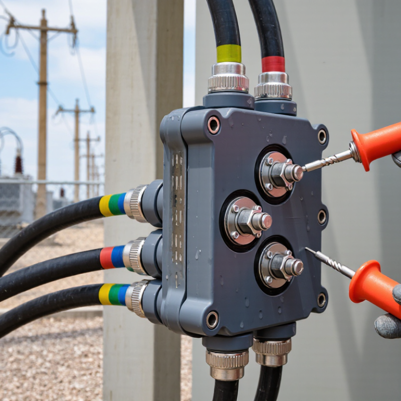
Choosing a 15kv 200a Loadbreak Junction requires more than matching voltage and current ratings. It requires a clear understanding of network conditions, operating practices, and installation constraints. In medium-voltage distribution systems, this compact component can influence switching safety, outage duration, and long-term maintenance.
Industry guidance provides a useful starting point. IEEE Std 386 defines interfaces and performance expectations for separable insulated connectors used in medium-voltage systems. CIGRE technical publications also emphasize insulation coordination, environmental exposure, and equipment reliability within distribution networks. The U.S. Energy Information Administration’s Form EIA-861 tracks reliability indicators such as SAIDI and SAIFI, reminding engineers that dependable components support wider system performance. Reports from the U.S. Department of Energy similarly highlight the need for resilient, maintainable distribution infrastructure.
Details matter. Check the continuous current rating, loadbreak capability, fault-current withstand, interface compatibility, insulation type, and grounding arrangement. A 200-amp rating alone does not prove suitability. The connector may face rain, salt mist, dust, ultraviolet exposure, or repeated switching near a transformer. Those conditions change the decision.
A practical selection process should compare manufacturer test data, certification records, installation instructions, and field experience. Do not rely only on a product photograph or a low purchase price. Sometimes, specifications appear complete but omit important interface details. That deserves a second review. This guide explains how to evaluate the 15kv 200a Loadbreak Junction against electrical requirements, environmental demands, safety practices, and lifecycle costs.
Choosing a 15kV 200A loadbreak junction starts with understanding both ratings. The 15kV class identifies the insulation and voltage category, not an exact operating voltage in every installation. Confirm the system’s maximum phase-to-phase voltage, insulation level, and required basic impulse level. A 200A rating usually indicates continuous current capacity under specified temperature conditions. It does not mean the junction can interrupt a 200A fault.
Loadbreak performance is a separate requirement. The connected elbow, bushing, and junction must be compatible as one tested system. Check the interface dimensions, cable insulation diameter, shielding arrangement, and grounding method. Review the manufacturer’s test data and the applicable industry standard, such as ANSI/IEEE 386, when relevant. Field installation also matters. Incorrect torque, contamination, or incomplete insertion can weaken the electrical connection. Small errors become serious underground.
Tips:
Check the voltage class first, then the continuous current rating.
Confirm the loadbreak operation rating and fault withstand rating separately.
Inspect the interface for moisture, cuts, or foreign material before energizing.
Use calibrated tools and follow the approved installation procedure.
A common mistake is treating 200A as a fault rating. It is not.
I would also recheck cable dimensions instead of trusting an old project record. Some records are incomplete, and assumptions can be costly.
When choosing a 15kV 200A loadbreak junction, verify IEEE Std 386 compliance before comparing price or enclosure size. The standard defines requirements for separable insulated connector systems used on distribution networks. Check the exact interface, mating dimensions, voltage class, and documented production tests. A generic “15kV rated” label is not enough.
The 95kV BIL rating gives insulation a defined impulse withstand level during lightning or switching surges. It does not replace proper grounding, shielding, or installation torque. Confirm that the complete junction assembly, not only one component, carries the 95kV BIL rating.
Also verify 200A continuous current through test records, conductor range, contact resistance, and temperature-rise results. Loose interfaces can create hot spots under normal feeder load. That failure may develop quietly.
EIA Form 861 reliability data reported roughly 137 minutes of average U.S. interruption duration in 2023, including major events. This figure shows why dependable sectionalizing equipment matters. It is not a direct prediction for one junction. Still, it supports careful verification of loadbreak performance and maintenance access. Field teams should review certificates, routine-test evidence, and installation instructions together. I would not rely on a catalog table alone. In practice, the overlooked detail is often the cable interface. Each configuration should be checked against the utility’s fault duty, grounding method, and switching procedure. Tens of minutes spent reviewing records can prevent a much longer outage.
How to Choose a 15kV 200A Loadbreak Junction?
A 15kV rating does not guarantee a correct fit. IEC 60502-2 commonly identifies this class as 8.7/15kV cable systems. Confirm the operating voltage, insulation level, and interface before checking dimensions. IEEE Std 386-2014 covers separable insulated connector interfaces, including 200A loadbreak applications. The junction must match the bushing, parking stand, and elbow interface. A 200A loadbreak connector should not be substituted with a 600A deadbreak design.
Cable selection needs more than conductor size. Compare the cable cross-section, insulation material, screen construction, and maximum insulation diameter. Two cables with identical conductor areas may have different jacket diameters. Measure the prepared cable, not only the catalogue value. For example, a 15kV cable may use an 8.7kV insulation class, but its screen and jacket can change the required stress-control components. Field installation records often reveal this mismatch late. I would recheck the diameter after stripping.
Grounding design deserves equal attention. Follow IEEE 80 principles for touch and step-voltage control, then verify the cable shield, concentric neutral, drain wires, and enclosure bonding path. The junction’s short-circuit rating must match the available fault current and clearing time. Do not assume the 200A continuous rating covers fault duty. A reliable specification should document interface type, cable range, insulation diameter, grounding method, and test evidence from qualified laboratories. Small details matter.
| Selection Dimension | Typical Requirement | Applicable Data or Matching Rule | Verification Before Purchase |
|---|---|---|---|
| 1. Electrical Rating and System Compatibility | |||
| Equipment class | 15 kV class | Suitable for medium-voltage systems up to approximately 15 kV line-to-line, commonly including 8.3/14.4 kV grounded-wye systems. | Confirm the system voltage, phase-to-ground voltage, grounding method, and the applicable utility or project specification. |
| Continuous current | 200 A | The complete junction assembly, bushing interface, connector, and cable must each be rated for at least 200 A continuous current. | Do not select a component solely because the cable ampacity exceeds 200 A; the separable interface rating must also be 200 A. |
| Insulation level | 95 kV BIL typical | A 15 kV class loadbreak interface commonly uses a 95 kV basic impulse insulation level. Switching and power-frequency withstand values must match the approved design. | Check the certified BIL, AC withstand, partial-discharge, and temperature ratings for the complete mating assembly. |
| Frequency | 50 or 60 Hz | Most 15 kV distribution applications operate at 50 Hz or 60 Hz, but the frequency must be compatible with the system and test documentation. | Verify frequency when the junction is used in an imported, industrial, or special-purpose distribution system. |
| 2. Interface Type and Mating Components | |||
| Primary interface | 200 A loadbreak separable interface | Use a junction designed for a standardized 200 A loadbreak bushing well, parking stand, feed-through insert, or equivalent mating component. | Confirm that the junction, bushing well, connector body, probe, and insulating cap belong to the same interface family and voltage class. |
| Loadbreak operation | Loadbreak-rated only | The connection may be operated under the manufacturer's specified loadbreak conditions using the correct operating tool and procedure. | Confirm whether the assembly is approved for load interruption, energized installation, dead-front operation, or only de-energized maintenance. |
| Fault-duty capability | System fault current dependent | Short-circuit withstand and fault-closing capability are separate from the 200 A continuous-current rating and must be adequate for the available fault current. | Compare the certified short-time and fault-closing ratings with the calculated system fault current and clearing time. |
| Mating geometry | Same dimensional interface | Key dimensions include contact-probe geometry, interface diameter, elbow seating depth, parking position, and insulating-cap fit. | Use dimensional drawings rather than nominal voltage or current labels alone; incompatible interfaces may not fully engage or seal. |
| 3. Cable Size and Insulation Diameter | |||
| Common cable conductor sizes | 1/0 AWG to 4/0 AWG typical | These conductor sizes are frequently encountered in 15 kV, 200 A distribution applications, but the correct size depends on ampacity, voltage drop, installation method, and fault duty. | Confirm conductor material, compact or compressed construction, strand count, shielding arrangement, and actual cable manufacturer's dimensions. |
| Typical insulation diameter band | Approximately 16–38 mm (0.63–1.50 in) | This is a practical screening range for many 15 kV shielded cables used with 200 A separable connectors. It is not a universal connector acceptance range. | Measure or obtain the actual diameter over the semiconductive insulation shield. Select a connector whose specified insulation-diameter range includes that value. |
| Example cable selection bands | Use only as an initial check | 1/0 AWG: approximately 16–28 mm insulation diameter 2/0 AWG: approximately 18–31 mm insulation diameter 4/0 AWG: approximately 22–38 mm insulation diameter | Actual dimensions vary with conductor compactness, insulation thickness, metallic shield, water-blocking layer, and jacket construction. Always use the cable data sheet for final selection. |
| Insulation thickness | 100% or 133% insulation level | 15 kV cables may use different insulation levels, commonly identified as 100% or 133%. The insulation thickness affects the cable diameter and stress-control fit. | Match the connector stress-control components to the actual cable insulation diameter, not just the conductor gauge. |
| Cable preparation | Manufacturer-defined strip dimensions | Critical preparation dimensions include jacket removal, shield cutback, semiconductive-screen removal, insulation length, and conductor exposure. | Use the approved preparation tool and dimensional chart. An incorrect screen cutback can cause electrical stress concentration or sealing failure. |
| 4. Grounding and Shielding Design | |||
| Cable shield type | Concentric neutral, copper tape, wire shield, or drain wire | The junction must provide a practical termination path for the cable metallic shield and maintain the intended grounding and bonding arrangement. | Identify the shield construction before ordering. Shield accessories and grounding leads are not interchangeable across cable designs. |
| Grounding lead | Separate grounding connection required | A flexible copper ground lead is commonly connected from the cable shield or concentric neutral to the system grounding point or equipment ground bar. | Verify conductor size, insulation type, connection hardware, routing, and the required minimum fault-current withstand. |
| Shield bonding method | Single-point or both-end bonding | Single-point bonding can reduce circulating shield current, while both-end bonding provides a low-impedance fault-current path. The correct method depends on the system design. | Follow the protection and grounding study. Do not change shield-bonding practice solely to simplify junction installation. |
| Grounding hardware | Corrosion-resistant, mechanically secure connections | Ground lugs, compression connectors, bonding clamps, and fasteners must be compatible with the shield material and the installation environment. | Check torque values, crimp tooling, conductor compatibility, corrosion protection, and accessibility for inspection. |
| Grounding continuity | Required before energization | The metallic shield, grounding lead, junction enclosure or bracket, and equipment grounding system should have verified electrical continuity. | Perform the required continuity and bonding tests, then document the results according to the project commissioning procedure. |
| 5. Environmental and Installation Conditions | |||
| Installation location | Indoor, outdoor, vault, or pad-mounted | Outdoor and below-grade applications require suitable sealing, UV resistance, pollution performance, water resistance, and mechanical protection. | Confirm enclosure rating, operating temperature, altitude, humidity, flooding exposure, salt contamination, and chemical exposure. |
| Cable bending radius | Per cable manufacturer's limit | The junction layout must allow the cable to enter without exceeding the minimum bending radius, especially near the connector stress-control area. | Check the cable's installation and final minimum bending-radius values and allow additional space for maintenance and testing. |
| Touch-safe construction | Dead-front design preferred | Insulated, shielded separable connectors reduce exposure to energized conductors when correctly installed with the required caps and accessories. | Confirm touch-safe requirements, exposed conductive parts, grounding provisions, and the approved operating procedure. |
| 6. Final Selection Checklist | |||
| Recommended selection sequence | Interface first, cable second, grounding third | 1. Confirm the 15 kV class and 200 A rating. 2. Match the 200 A loadbreak interface and mating components. 3. Confirm the cable conductor size and actual insulation diameter. 4. Select the correct stress-control and sealing components. 5. Define shield bonding and grounding accessories. 6. Verify environmental, fault-duty, and installation requirements. | All dimensions and ratings must be verified against approved technical drawings |
| Important engineering note | Nominal values such as “15 kV” and “200 A” do not guarantee compatibility. Final selection must be based on the actual bushing interface, certified electrical ratings, cable insulation diameter, cable preparation dimensions, shield construction, grounding design, and installation conditions. | ||

A 15kV, 200A rating is only the starting point. Confirm the junction’s loadbreak duty for the actual switching task. Continuous current and interrupting current are different values. Review the tested loadbreak current, voltage class, and switching frequency. A connector suitable for occasional feeder isolation may not suit repeated sectionalizing. Do not guess. Check the manufacturer’s test data and applicable utility specifications, such as IEEE 386 requirements.
Fault-close performance deserves equal attention. The junction must withstand accidental energization onto a fault without separating or creating a dangerous failure. Compare the available fault current with the marked fault-close rating, including its test duration and current basis. Short-circuit calculations can be misunderstood when peak and symmetrical RMS values are mixed. That shortcut feels efficient, but it can produce an unsafe selection. Have the system engineer verify the calculation.
Shielding is not cosmetic. Confirm the cable insulation diameter, shield design, grounding method, and interface compatibility. A properly bonded conductive shield controls the electric field and supports touch-safe operation. Inspect the elbow, junction body, and cable screen as one system. Fit matters. A mechanically connected part may still have poor electrical continuity. Field conditions also matter, including moisture, cramped vaults, and contaminated surfaces. I would leave room for review here, because installation drawings often omit small grounding details that later become critical.
How to Choose a 15kV 200A Loadbreak Junction?
Installation conditions should guide the selection, not catalog dimensions alone. Check phase spacing, enclosure depth, cable bending radius, soil moisture, and available fault current. A 15kV, 200A junction must match the cable insulation, interface class, and operating environment. IEEE Std 386 defines requirements for separable insulated connectors used in distribution systems. Field experience shows that poor cable support often creates more trouble than the junction itself. Fit matters.
Accessories deserve equal attention. Include parking stands, grounding kits, elbow connectors, insulating caps, and voltage-sensing provisions where required. Confirm compatibility before delivery. A missing accessory can delay energization and expose technicians to unnecessary work. The U.S. Department of Energy reports that distribution systems contribute roughly 90% of customer interruptions. That figure makes dependable accessories more than a convenience. It is easy to underestimate them.
Testing should follow the utility’s procedures and NETA ATS guidance, including visual inspection, torque verification, phasing, insulation checks, and grounding continuity. Do not rely on one test result. A clean reading can still hide installation damage. For lifecycle cost, compare purchase price, outage exposure, inspection labor, spare-part needs, and replacement access. DOE grid modernization reports emphasize aging distribution assets and rising reliability pressure. The cheapest junction may not remain cheap. I would document actual installation hours and failures, then revise the specification after each project. That reflection is often missing.
Compare installation conditions, accessories, testing requirements, and lifecycle cost before selecting a 15 kV class, 200 A loadbreak junction.
The chart shows a practical procurement weighting for a typical medium-voltage project. Installation conditions receive the highest weighting because enclosure environment, cable configuration, grounding, clearances, and accessibility directly affect product suitability. Accessories, testing, and lifecycle cost should then be verified against applicable project specifications and IEEE 386 requirements. The electrical baseline is a 15 kV class interface with a 200 A loadbreak rating; actual ratings, short-circuit withstand, environmental limits, and maintenance intervals must be confirmed from the selected product documentation.
All products and services provided by Innovative Plastic Molders, Inc. will meet or exceed our customer's perceived requirements and expectations. We will listen and respond to what our customers are telling us in a timely and forthright manner.

ISO 9001:2015 CERTIFIED
© Copyright 2009 – Innovative Plastic Molders, Inc.
Website by Central 8 Marketing
10451 Dog Leg Road Ste 200
Vandalia, OH 45377
Phone: 937.898.3775
Fax: 937.535.0640
Email: sale@endtheplastic.com