

Choosing the right Battery Liquid Cooling Pipe in 2026 is no longer a minor component decision. Electric vehicle production is expanding rapidly. The International Energy Agency’s Global EV Outlook 2025 expects more than 20 million electric cars to be sold worldwide in 2025, representing over one-quarter of global car sales. BloombergNEF’s Electric Vehicle Outlook 2025 also forecasts continued battery demand growth, increasing pressure on thermal-management suppliers.
Higher energy density creates tighter thermal limits. A cooling pipe must move coolant evenly, resist vibration, and maintain reliable sealing near hot battery modules. Its material, inner diameter, wall thickness, bend radius, and connection method all affect performance. Aluminum tubes may offer strong heat transfer and low weight. Polymer or multilayer designs can simplify routing. Neither option is automatically better.
Look beyond the brochure.
A practical selection process should examine coolant compatibility, pressure cycling, burst strength, permeability, corrosion resistance, and long-term fatigue. SAE and ISO test methods can support validation, but laboratory results never replace vehicle-level testing. Temperature mapping, leak inspection, and vibration trials should reflect real driving conditions.
A neat specification sheet can still hide a weak tube. This is where buyers sometimes move too quickly. Cost reductions may create thinner walls, tighter bends, or less reliable joints. The better question is not only, “Can this pipe cool the battery?” It is, “Can it keep cooling safely after years of heat, vibration, assembly variation, and winter exposure?” This guide explains the evidence, testing details, and supplier questions needed to make that decision with greater confidence in 2026.
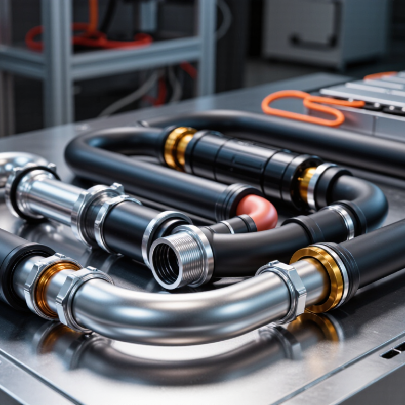
How to Choose Battery Liquid Cooling Pipes in 2026?
Battery liquid cooling pipes transfer heat away from cells during charging, driving, and fast acceleration. Coolant enters a manifold, moves through parallel channels, absorbs heat, then returns to a chiller or radiator. This controlled circulation reduces temperature differences between cells. It also protects battery life and charging performance.
The need is growing quickly. The IEA’s Global EV Outlook 2024 reported nearly 14 million electric car sales in 2023, representing almost 18% of global new-car sales. BloombergNEF’s 2024 battery price report recorded an average pack price of 115 dollars per kilowatt-hour, down 20% year on year. Denser packs create tighter thermal demands. Pipe selection now requires more than a large flow rate. Check pressure drop, bend radius, wall thickness, vibration resistance, and coolant compatibility. A pipe can look efficient on paper but fail near a sharp module corner. That mistake is easy to underestimate.
Tips: Select low-permeation materials and reliable seals. Match pipe diameter with pump capacity, not guesswork. Test hot and cold cycles. Include leak detection. Non-conductive coolant may reduce electrical risk, but it still demands careful compatibility testing. No design is perfect. Reflect on service access, because a hidden pipe can make future repairs unnecessarily difficult.
How to Choose Battery Liquid Cooling Pipes in 2026?
Key Performance Requirements for Battery Cooling Pipes
Battery cooling pipes must control heat steadily under changing loads. During design reviews, engineers often focus on flow rate first. That can be a mistake. Temperature uniformity, pressure stability, and long-term material behavior matter just as much. A suitable pipe should support the required coolant flow without creating excessive pump demand. It also needs a low thermal resistance path between the coolant and battery modules.
Check the operating temperature range carefully. Some systems face cold starts below freezing and repeated heat cycles above normal conditions. The pipe should resist cracking, swelling, and loss of flexibility across these changes. Burst pressure must exceed the maximum working pressure with a clear safety margin. Pay attention to bending radius, vibration resistance, and connection strength near tight module layouts. Small leaks can cause serious downtime.
Material compatibility deserves direct testing. Coolant additives, moisture, and metal interfaces may accelerate aging. Inspect permeation rates, cleanliness, and electrical insulation where necessary. In production, pressure testing and dimensional checks should be traceable for every batch. I have seen attractive prototypes fail after repeated bending, even when their laboratory flow results looked excellent. That weakness deserves honest review. No single specification fits every battery pack. Field temperature data should guide the final selection.
How to Choose Battery Liquid Cooling Pipes in 2026?
Battery demand reached about 750 GWh in 2023, according to the International Energy Agency’s Global EV Outlook 2024. That growth makes pipe selection more demanding. Start with coolant compatibility, operating temperature, pressure, and vibration exposure. Aluminum offers low mass and thermal conductivity near 205 W/m·K. Copper conducts better, near 390 W/m·K, but adds weight and galvanic corrosion risks. Stainless steel conducts less heat, yet provides strong pressure and chemical resistance. Polymer or multilayer pipes can reduce weight, but permeation and aging need careful testing.
Size changes performance quickly. Measure internal diameter, not only the outside diameter. A smaller bore increases velocity and pressure loss. A larger bore lowers resistance but may reduce packaging efficiency. Use the expected flow rate, coolant viscosity, bend radius, and pump curve together. The U.S. Department of Energy’s Vehicle Technologies Office emphasizes temperature uniformity as a key battery-management concern. A pipe that cools one area well may still create uneven cell temperatures.
Tips: Request burst, pulse-pressure, vibration, and coolant-aging data. Compare thermal resistance across the complete assembly, including fittings. Do not trust conductivity alone. It can mislead. Field experience also matters: a technically efficient pipe may fail installation checks when its bend radius is too tight. SAE thermal-management guidance supports validation under realistic duty cycles, but every battery layout remains different. That is where early prototype testing becomes essential.
How to Choose Battery Liquid Cooling Pipes in 2026?
Selecting the right liquid cooling pipe begins with the battery pack structure. Cylindrical cells often suit serpentine pipes or parallel branch layouts. These designs can follow compact cell rows with consistent contact pressure. However, long serpentine paths may create higher pressure drops. Pump capacity must be checked early.
Prismatic packs usually need wider channels across large cell faces. Flat pipes can improve contact and reduce thermal gaps. Their larger surfaces also demand careful support against vibration. Pouch cells require gentler compression and flexible routing. Thin, closely spaced pipes can cool their broad surfaces without creating sharp stress points. Keep bend radii generous. Small bends can become future leak risks.
In prototype testing, I would measure inlet and outlet temperatures across every module. A five-degree difference deserves investigation. Uneven flow often hides behind acceptable average temperatures. Pipe material, wall thickness, joint quality, and coolant compatibility need documented verification. Pressure testing, thermal cycling, vibration testing, and leak inspection should follow realistic pack conditions. A perfect layout rarely exists. Designers may still underestimate assembly access or thermal expansion. That mistake is easy to make. Leave room for service tools, sensors, and manufacturing tolerances. Reliable pipe selection balances cooling performance, hydraulic resistance, durability, and production practicality.
| Battery Pack Structure | Typical Cooling Challenge | Recommended Pipe Design | Common Tube Material | Typical Outer Diameter | Typical Wall Thickness | Recommended Routing | Key Selection Criteria | Main Advantages | Important Limitations |
|---|---|---|---|---|---|---|---|---|---|
| Cylindrical-cell modules | Many small cells create repeated heat sources and limited space between cell rows. | Flat serpentine pipe or multi-channel cooling plate positioned beneath the cell array. | Aluminum alloy or brazed aluminum multi-channel plate. | 6–12 mm for round tubes; 1.5–3.0 mm channel height for flat plates. | 0.6–1.2 mm for aluminum tubes; design-specific for plates. | Use parallel passages where possible to reduce flow length and temperature variation. | Low bend radius, uniform contact, vibration resistance, and balanced flow distribution. | Good coverage of dense cell layouts; relatively simple module integration. | Sharp bends can increase pressure loss; uneven flow may create cell-to-cell temperature differences. |
| Prismatic-cell modules | Large flat cell faces require consistent surface contact and controlled compression. | Flat extruded tube, bonded cooling rail, or cooling plate between cell rows. | Aluminum alloy, selected for thermal conductivity and low mass. | 8–20 mm equivalent hydraulic diameter, depending on the plate or rail design. | 0.8–1.5 mm for formed or extruded aluminum sections. | Place cooling surfaces along the broad cell faces; keep manifolds outside the compression zone. | Flatness, thermal interface resistance, allowable cell expansion, and assembly tolerance. | Large contact area and predictable thermal paths for broad rectangular cells. | Rigid plates can increase packaging mass; improper compression may damage cells or reduce contact. |
| Pouch-cell modules | Flexible cell surfaces, swelling, and strict limits around tabs and sealing edges. | Thin cooling plates or compliant flat channels placed between adjacent cells. | Aluminum cooling plate with a polymer or elastomeric interface layer. | 1.5–4.0 mm channel thickness for compact inter-cell plates. | Typically 0.5–1.0 mm metal wall, subject to forming and pressure requirements. | Avoid direct contact with pouch edges and tabs; provide compliant supports for expansion. | Flexibility, electrical isolation, leak protection, compression control, and tab clearance. | Excellent surface coverage with low thermal resistance when the interface is uniform. | Rigid plumbing and poorly controlled clamping can cause local stress or abrasion. |
| Cell-to-pack (CTP) structure | Few internal module boundaries leave limited routing space and make service access more difficult. | Integrated full-length cooling plate with parallel channels and external manifolds. | Brazed or welded aluminum multi-channel plate. | 8–25 mm equivalent hydraulic diameter, selected through thermal and flow analysis. | Approximately 0.8–1.5 mm for common formed aluminum structures. | Use short parallel circuits, accessible inlet and outlet manifolds, and protected perimeter routing. | Low pressure drop, structural stiffness, sealing reliability, and pack-level repair strategy. | High packaging efficiency and consistent cooling across a large battery area. | A plate failure can affect a large area; manufacturing flatness and leak testing are critical. |
| Cell-to-chassis structure | The cooling system also contributes to vehicle-floor stiffness, sealing, and impact protection. | Structural cooling tray with embedded channels or a reinforced flat-tube network. | Aluminum alloy tray with brazed or mechanically joined cooling channels. | 10–30 mm equivalent hydraulic diameter, depending on structural depth. | Around 1.0–2.0 mm in structural channel sections, subject to crash and fatigue analysis. | Keep joints away from impact-prone zones and use protected service connections. | Crash durability, fatigue life, corrosion resistance, sealing, and thermal uniformity. | Combines thermal management and structural functions while saving underbody space. | More complex validation, difficult repair access, and higher consequences of a leak. |
| High-power or fast-charging pack | High transient heat generation requires rapid heat removal without excessive pumping power. | Parallel micro-channel plate or short-path dual-circuit cooling network. | Aluminum alloy; stainless steel may be considered for specific connection requirements. | 4–15 mm equivalent hydraulic diameter, optimized by flow simulation. | Approximately 0.6–1.2 mm for compact metal channels. | Divide long packs into balanced circuits and place sensors near thermal hotspots. | Heat-transfer coefficient, pressure drop, coolant velocity, hotspot control, and pump capacity. | Supports high heat flux and fast temperature response when properly balanced. | Small channels are more sensitive to contamination, blockage, and manufacturing variation. |
| Removable serviceable module | Connections must tolerate repeated assembly while maintaining a reliable seal. | Flexible hose sections combined with rigid formed tubes and accessible quick-connect interfaces. | EPDM or equivalent coolant hose with aluminum or stainless-steel rigid sections. | 8–16 mm nominal hose or tube diameter for module-level circuits. | Hose wall commonly 2–4 mm; rigid-section thickness is application-specific. | Provide strain relief, bend supports, drip control, and clear access to service fittings. | Seal life, coolant compatibility, vibration resistance, minimum bend radius, and service cycle count. | Simplifies module replacement and accommodates assembly tolerances. | Flexible hoses occupy more space and may have higher permeation or aging risk than metal channels. |
How to Choose Battery Liquid Cooling Pipes in 2026?
Installation, Safety, Testing, and Maintenance Considerations
Choosing battery liquid cooling pipes requires more than checking diameter and flow rate. The pipe must match the coolant, operating temperature, pressure, and battery enclosure materials. During installation, keep the approved bend radius. A sharp bend can restrict flow or weaken the wall. Use clean caps until connection. Even a small particle may damage a pump or valve.
Safety begins with isolation. Confirm that the cooling circuit cannot contact energized components during service. Secure pipes away from busbars, sharp brackets, and hot surfaces. Add abrasion protection where vibration occurs. Connections should receive controlled tightening, not excessive force. A torque record improves traceability. It also exposes weak installation habits. Leak sensors near joints provide useful early warning, especially beneath battery modules.
Testing should include visual inspection, pressure testing, flow verification, and thermal cycling. Use the test medium and pressure approved for the pipe system. Never assume a successful pressure test proves long-term reliability. Check for pressure loss, trapped air, uneven temperatures, and connector movement. During maintenance, inspect discoloration, swelling, cracks, and hose stiffness. Review pump data and temperature logs at planned intervals. Replace damaged seals immediately. Small leaks rarely remain small.
A perfect checklist is impossible. Real installations contain dust, vibration, and rushed repairs. Therefore, record every change, test result, and abnormal sound. This evidence supports safer decisions when the system behaves differently next season.
All products and services provided by Innovative Plastic Molders, Inc. will meet or exceed our customer's perceived requirements and expectations. We will listen and respond to what our customers are telling us in a timely and forthright manner.

ISO 9001:2015 CERTIFIED
© Copyright 2009 – Innovative Plastic Molders, Inc.
Website by Central 8 Marketing
10451 Dog Leg Road Ste 200
Vandalia, OH 45377
Phone: 937.898.3775
Fax: 937.535.0640
Email: sale@endtheplastic.com

