

Choosing the best Power Transformer Fuse for 2026 starts with the transformer, not the catalog. Voltage class, available fault current, inrush, and the protection scheme all matter. A fuse that clears a fault quickly may still leave a dangerous gap in protection if its characteristics do not coordinate with upstream devices. Small details count: the nameplate, the transformer’s inrush curve, and the fuse holder’s rating.
The U.S. Department of Energy’s report, Large Power Transformers and the U.S. Electric Grid, describes the operational importance and supply challenges of large transformers. CIGRE’s transformer reliability work examines failure patterns and equipment performance. Neither supports a universal “best” fuse. IEEE C37.48 offers application guidance for high-voltage fuses, while IEEE C57.109 addresses transformer through-fault protection. Together, these references point to coordination and application—not fuse type alone—as the basis for a sound choice.
A useful line often attributed to transformer-protection specialist Thomas A. Short is: “The fuse is the simplest and least expensive protective device available.” Simplicity is not enough. Expulsion fuses, current-limiting fuses, and full-range designs behave differently under fault conditions. The right selection must match the transformer and the system around it. This guide compares those options for 2026, including their limits, maintenance needs, and practical trade-offs. Some projects still lack complete fault data. That uncertainty deserves attention, not a confident guess.
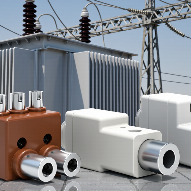
A transformer fuse must interrupt damaging overcurrents while allowing normal energization and temporary load variations. Its job is not simply to “blow fast.” It must also coordinate with upstream relays and downstream devices, limiting unnecessary outages.
IEEE Std C37.91-2021 describes transformer protection considerations, including magnetizing inrush, which can reach roughly 8–12 times rated current. That brief surge can resemble a fault. A fuse curve that ignores it may operate during routine switching.
High-voltage current-limiting fuses can restrict peak fault current, while expulsion fuses commonly provide a simpler, economical option. Some installations use a backup fuse with a low-voltage breaker; the combination must be checked across the full fault-current range.
IEC 60282-1 sets requirements for high-voltage current-limiting fuses, but compliance alone does not establish suitability for a specific transformer. Engineers should compare the fuse’s minimum-melting and total-clearing curves against transformer damage limits, inrush behavior, available fault current, and connected protection.
Details matter. A dusty outdoor cutout, a cold morning energization, or a changed feeder relay setting can alter real-world performance. IEEE guidance supports evaluating these operating conditions rather than selecting by nameplate current alone.
Still, coordination studies can rely on assumptions that later prove imperfect. Recheck settings after system changes, and document the basis for fuse ratings and replacement choices.
Power transformer applications use several fuse arrangements, each suited to different fault levels and operating conditions. Expulsion fuse links, commonly installed in cutouts, interrupt faults by releasing gases that help extinguish the arc. They are practical on overhead distribution systems, but their interrupting capacity and coordination must match the available fault current. Internal oil-immersed fuses are compact, though replacement may require opening the transformer tank. That changes maintenance planning.
Current-limiting fuses restrict peak fault current and can protect transformers where prospective fault levels are high. Backup current-limiting fuses are often paired with low-current expulsion links: one handles severe faults, while the other responds to lower-level faults and overloads. The selection process should check transformer inrush, rated voltage, fuse minimum-melting curves, and coordination with upstream protection. IEEE C37.48 provides application guidance, while IEC 60282-1 covers high-voltage current-limiting fuses. A chart alone is not enough.
System growth makes careful coordination more consequential. The International Energy Agency’s 2023 report, Electricity Grids and Secure Energy Transitions, says annual grid investment needs to exceed USD 600 billion by 2030, up from about USD 300 billion. That is grid-wide context, not a fuse-sizing rule. Not always. Field conditions, including ambient temperature and transformer loading, can shift the practical choice. Engineers should verify settings against current fault studies; even a well-matched fuse can leave avoidable outages if coordination is overlooked.
What Is the Best Power Transformer Fuse Type for 2026?
Key Factors in Selecting a Transformer Fuse
The best fuse depends on the transformer, the available fault current, and the protection devices around it. An expulsion fuse may suit an outdoor distribution transformer where fault levels and operating practices support its use. A current-limiting fuse can reduce fault energy, which may matter in compact installations with high available fault current. Neither choice is automatically right.
Start with the transformer’s voltage and kVA rating, then check its primary full-load current and expected magnetizing inrush. A fuse must tolerate normal energization without nuisance operation while still coordinating with upstream and downstream protection. Review time-current curves against the transformer damage curve and the secondary protective device. Small details matter. A rating chosen from full-load current alone can miss inrush or coordination concerns.
Also confirm the prospective fault current at the installation point and the fuse’s interrupting rating. For backup current-limiting fuses, verify which lower-current faults another device must clear; these fuses do not necessarily interrupt every fault current. Check the installation environment, enclosure, and the equipment manufacturer’s stated limits. Field conditions can differ from a tidy calculation. I would recheck assumptions with measured or utility-provided data and have a qualified protection engineer review the final selection.
How to use this chart: 11, 13.8, 22 and 33 kV are examples of nominal distribution system voltages, not fuse ratings or recommendations. Select a fuse with an appropriate rated voltage and interrupting capacity, then check transformer inrush, expected fault current and protection coordination. Expulsion, current-limiting and backup fuses suit different applications; no single type is best for every transformer.
What Is the Best Power Transformer Fuse Type for 2026?
Comparing Fuse Performance Across Operating Conditions
A transformer fuse must handle more than a single fault-current value. During energization, magnetizing inrush can briefly rise far above normal load current. A fuse that responds too quickly may open during a routine switch-on. That is disruptive. Engineers compare time-current curves with expected inrush, load growth, and downstream protection, rather than choosing by rating alone.
Expulsion fuses can interrupt certain fault conditions while venting gases, so installation location and enclosure design matter. Current-limiting fuses restrict peak fault current and can suit systems with high available fault levels. Backup fuses, however, may need a coordinated device to clear lower-current faults. The details are not always neat. Two installations with similar transformers can require different protection because their source impedance and coordination needs differ.
Operating temperature also changes the comparison. A hot cabinet, poor ventilation, or sustained loading may affect fuse performance and service life. Check the manufacturer’s published curves and limits for the actual mounting conditions. Then verify coordination with upstream and downstream devices, including expected fault levels and transformer inrush. A field inspection can reveal dust, corrosion, or loose connections that a calculation misses. I would not call one fuse type “best” without those site details; that answer can look tidy on paper and still fail in service.
| Fuse type | Typical transformer application | Transformer energization and inrush | Overload and low-current faults | High-current short circuits | Environmental and installation considerations | Key selection trade-off |
|---|---|---|---|---|---|---|
| Expulsion (dropout) fuse | Commonly used as an outdoor primary fuse on distribution transformers and overhead circuits. | A correctly selected fuse link can ride through expected magnetizing inrush; the time-current curve must be checked against transformer inrush and load. | Can interrupt overload and fault currents within its rated operating range. Protection sensitivity depends on the fuse-link rating and coordination. | Interrupts faults within its specified voltage and interrupting-current ratings, but generally does not provide the same current-limiting effect as a current-limiting fuse. | Interruption produces gases and may eject hot particles. Installation requires suitable outdoor clearances and attention to the device’s venting and safety requirements. | Simple, visible operation and commonly used outdoors; verify interrupting capacity, coordination, and the consequences of venting. |
| Backup current-limiting fuse | Often installed in series with another protective device for transformer primary protection, particularly where available fault current is high. | Selection must allow for expected inrush and coordinate with any series device; the fuse’s minimum melting current and time-current curve matter. | Has a specified minimum interrupting current and may not safely clear currents below that threshold. A series device is needed to clear the lower-current range. | Limits fault-current peak and let-through energy when operating in its current-limiting range, reducing thermal and mechanical stress. | Usually installed in an appropriate enclosure or fuse assembly. Confirm voltage, interrupting rating, and the complete series-protection arrangement. | Strong high-fault-current limitation, but it is not a stand-alone solution for all fault currents. |
| Full-range current-limiting fuse | Used where a single fuse is intended to interrupt currents from its specified minimum interrupting current up to its rated maximum interrupting current. | Must be selected so its time-current characteristics tolerate expected transformer inrush and coordinate with upstream and downstream protection. | Unlike a backup-only fuse, a properly rated full-range design is intended to interrupt the range from its stated minimum through its maximum rating. Confirm the actual published ratings. | Limits peak current and let-through energy in its current-limiting operating range. | Requires installation in equipment designed for the fuse’s voltage, heat dissipation, and fault-duty conditions. | Broad interruption range and effective high-fault limitation; the specific minimum interrupting rating and coordination still require verification. |
| Dual-element, time-delay fuse | Commonly used on low-voltage transformer secondary circuits; selected primary applications depend on the fuse’s voltage rating and protective-device design. | The time-delay element can help avoid nuisance operation during short-duration inrush, provided the selected curve suits the transformer. | Provides time-delayed response to some overloads and faster operation at higher fault currents, depending on its time-current characteristics. | Interrupting performance depends on the fuse’s rated voltage and interrupting capacity; current limitation is not guaranteed unless specified for that fuse. | Use only in equipment and circuits within its marked voltage, current, and interrupting ratings. Low-voltage fuse ratings are not suitable for medium-voltage primary circuits. | Useful where inrush tolerance and overload response are priorities; confirm that the fuse is designed and rated for the intended transformer side. |
| Selection note: There is no universally best fuse type. Choose from the transformer’s voltage and kVA, expected inrush, available fault current, grounding and system configuration, load profile, protective-device coordination, and applicable electrical codes. Verify the exact fuse ratings and time-current curves for the specific installation. | ||||||
There is no single best power transformer fuse for every installation. Selection depends on transformer voltage, rating, available fault current, and the protection devices around it. A fuse must tolerate magnetizing inrush while clearing faults before transformer damage becomes likely. That balance matters.
Standards guide the choice. IEC 60282-1 covers high-voltage current-limiting fuses; applicable IEEE C37 requirements may also apply. In 2026, engineers should check the editions adopted by the local authority and utility, rather than assume a standard has not changed. They should verify rated voltage, interrupting capacity, and time-current behavior against the transformer’s damage curve. A current-limiting fuse can reduce fault energy, but may need a coordinated backup device. Expulsion fuses can suit some outdoor distribution installations, yet their operating conditions and system fault level must be reviewed.
Field details can change the answer. Record the transformer nameplate, tap setting, expected inrush, and upstream relay or fuse curves. Check coordination for both low-side and high-side faults. A neat table can still miss a long feeder or an unusual load cycle. It happens. Have a qualified engineer review the final selection, then document the assumptions and test requirements.
All products and services provided by Innovative Plastic Molders, Inc. will meet or exceed our customer's perceived requirements and expectations. We will listen and respond to what our customers are telling us in a timely and forthright manner.

ISO 9001:2015 CERTIFIED
© Copyright 2009 – Innovative Plastic Molders, Inc.
Website by Central 8 Marketing
10451 Dog Leg Road Ste 200
Vandalia, OH 45377
Phone: 937.898.3775
Fax: 937.535.0640
Email: sale@endtheplastic.com

